
Begin with a measured site plan
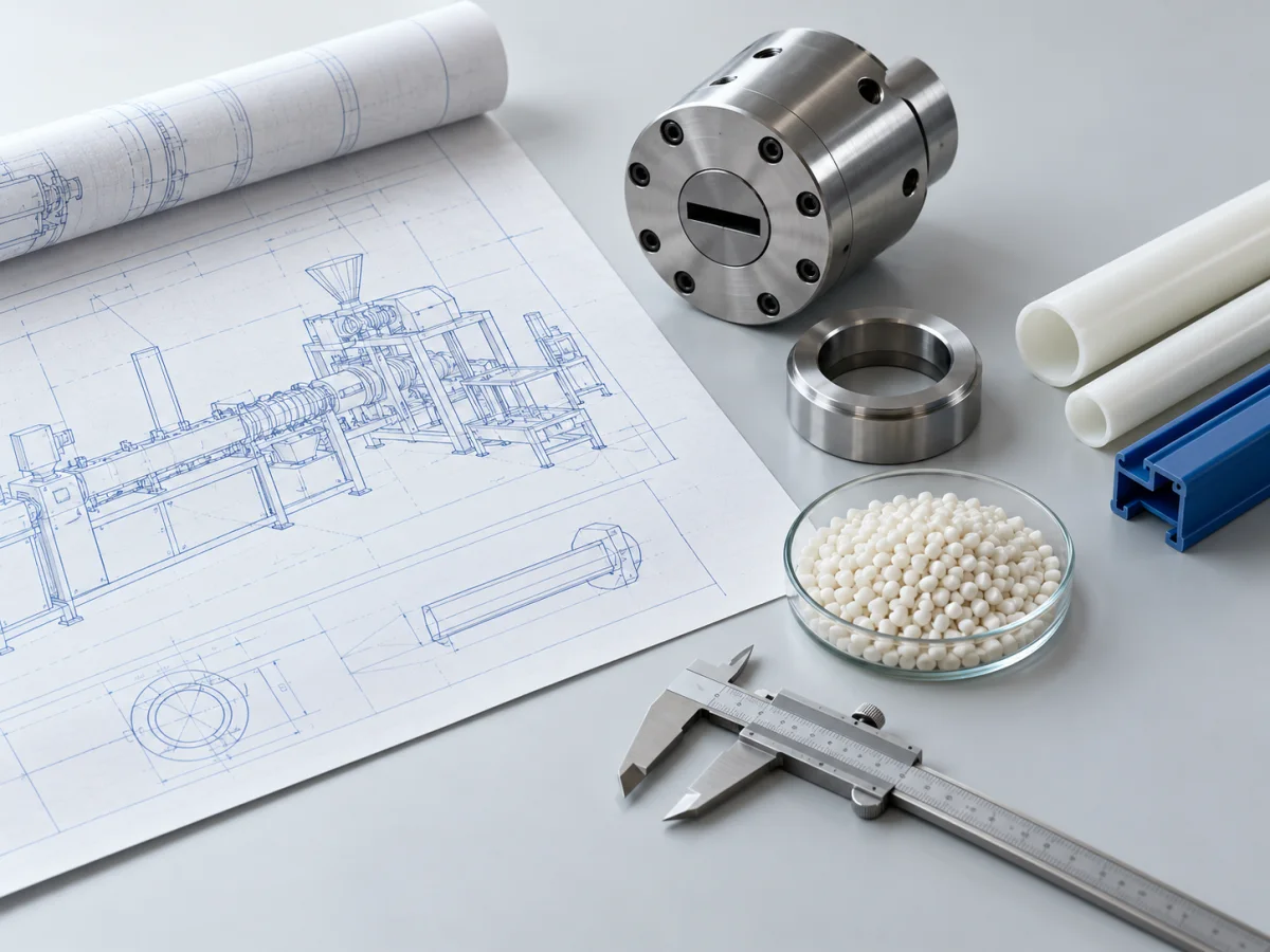
A plastic recycling plant setup needs more than the outline of its main machine. The usable installation includes feedstock storage, preparation interfaces, operator positions, service access and finished-pellet removal. Start with a measured plan showing columns, doors, fixed equipment and the boundaries of the proposed production area. Record overhead restrictions and delivery access where they affect installation or routine equipment handling.
Mark what is measured and what remains provisional. Photographs help explain the space, but they should accompany dimensions rather than replace them. Give the layout a revision number and a responsible owner. When the proposal changes, that owner can check whether a longer tank, different feed arrangement or relocated service point affects the rest of the plan.
Follow the material from arrival to dispatch
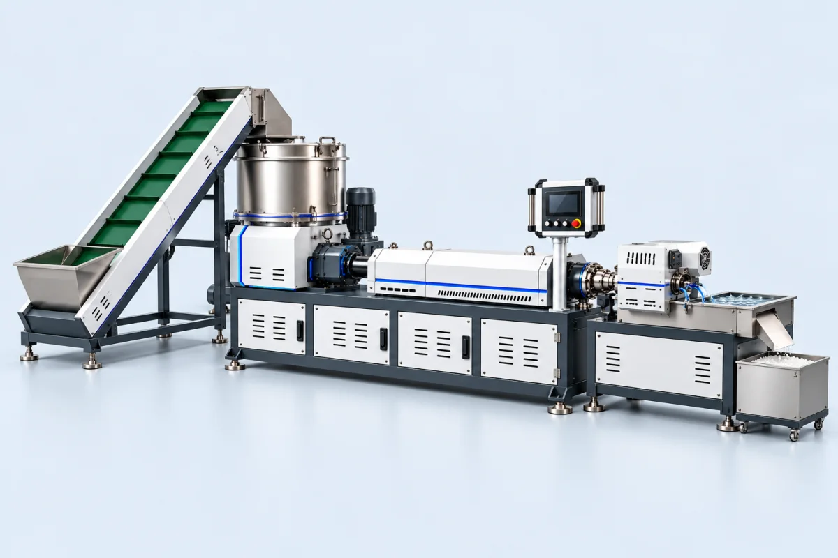
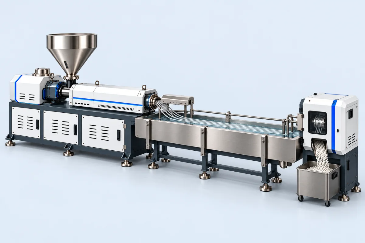
Draw the route for incoming scrap, preparation, recycling, pellet inspection, packing and storage. Identify the container or handling method used at each step. Film bales and rigid regrind bins create different movements and replenishment needs. Show any preparation stages supplied separately, such as sorting, size reduction, washing or drying, with a defined handover condition. Include how rejected feed, startup scrap and maintenance waste leave the production area.
Look for crossings between material movement and operator work. A process that appears linear on paper may require repeated forklift visits or manual transfers in practice. Discuss those movements with the people who will operate the line. The goal is a workable handling plan, not a particular factory shape or a claim that one arrangement is always the most efficient.

Show the buffers, not just the machines
Processing stages do not always start, stop or change over together. Identify where material can wait and what condition it must retain while waiting. A washing line, prepared-feed store, extrusion stage and packing operation may have different schedules. The layout should make their interfaces visible and avoid relying on unlimited floor storage as an unspoken buffer.
State how incoming lots and finished product will be identified and separated. Include space for samples, quarantined material and products awaiting acceptance where your operating workflow requires it. These areas may be modest, but omitting them forces decisions after installation. Ask whether the proposed storage method also supports the preparation conditions assumed in the equipment brief.
Draw the service envelope
Ask suppliers to show more than the equipment's operating outline. Identify the space needed to open cabinets, change screens, remove tooling and access wear components. Where a screw or other long component must be withdrawn, review its removal route and handling method. The correct dimensions depend on the supplied equipment, so obtain them from the project drawings.
Include routine cleaning and inspection tasks in the same review. A service point that is technically reachable may still be inconvenient once a conveyor or storage bin is installed beside it. Invite maintenance personnel to walk through the proposed work sequence. Record unresolved access questions before the layout is used as the basis for civil or utility work.
Make utility responsibility visible
Locate electrical, cooling-water, compressed-air, drainage and extraction connections as required by the proposed process. Show the routing concept and identify which party designs and supplies each part. Ask for connection requirements, expected operating conditions and any constraints that affect routing. A list of utilities without locations is not enough to coordinate an installation.
Check shared services against other plant loads and realistic ambient conditions. The available electrical or cooling capacity should be confirmed by the responsible site team. Water treatment, discharge arrangements and any site-specific approvals also need an owner. This is a coordination checklist, not a substitute for detailed facility engineering or the applicable local requirements.
| Drawing layer | What must be shown | Review owner |
|---|---|---|
| Material movement | Incoming scrap, prepared feed, accepted pellets and rejected material routes | Production and logistics |
| Equipment and service | Operating positions, cabinet access, component removal and maintenance zones | Supplier and maintenance team |
| Utilities | Connection locations, routing concept, operating assumptions and by-others scope | Site engineering |
| Installation | Delivery route, handling needs, temporary storage and readiness items | Project coordinator |
Scroll horizontally to compare all columns.
Review how the equipment reaches its position
Trace the installation route from delivery point to final location. Check doors, turning space, floor condition, lifting arrangements and temporary storage. Ask the supplier for the relevant shipping and handling information for the selected configuration. Do not infer those details from a promotional photograph or from a machine of a similar name.
Agree who receives, unloads, positions and connects the equipment, and what must be ready before installation support begins. Keep temporary installation needs separate from the final operating layout. If an existing line must remain active during the work, document the interfaces and sequence with the plant team. Unclear responsibilities can create delays even when every machine arrives as expected.
Approve a coordinated drawing and an action list
Before approval, review the same drawing with production, maintenance, utilities and purchasing. Check material routes, access, connection points, product removal and the limits of each supplier's scope. Keep a short action list naming the unresolved item, its owner and the evidence needed to close it. A drawing marked approved should not conceal important dimensions that are still assumed.
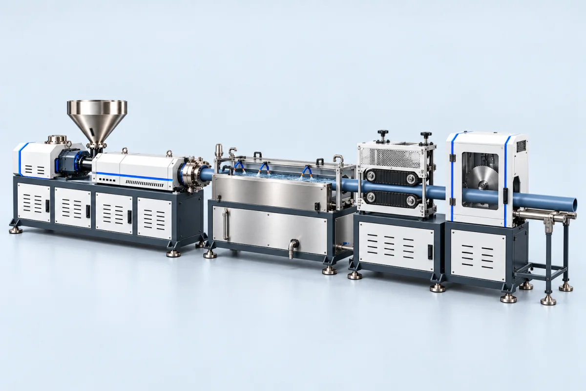
For an ARKPM recycling proposal, share the measured plan, the material flow and the features that cannot move. Include which preparation equipment already exists and where its responsibility ends. The final arrangement should connect the feedstock brief to the site responsibilities and acceptance plan. Where a project also includes an extrusion line, prepare its product and downstream requirements as a separate connected scope instead of assuming it shares every recycling-line utility condition.
Further technical reading
Manufacturer documentation can help explain process principles. These references do not describe ARKPM equipment or establish ARKPM performance claims.